2022-4-18
Chip resistors
Technical information
Example of chip resistor adoption (2)
- High heat resistance chip resistors have enabled compact-sizing and long operating life of inverters and BMS -
Download this article
![]()
Toward achieving a low carbon society, every country is starting regulation enhancement by assuming an EV-based social shift. Some countries and regions, such as several countries in Europe, the State of California in the U.S., and Quebec in Canada, have already announced the prohibition of new sales of gasoline-powered vehicles and diesel-driven vehicles in 2035. China, which became a big automobile country, sets a target to make all automobiles EVs in 2035, while Japan is also targeting all new cars to be EVs (including hybrid vehicles) by 2035.
While anticipating an explosive increase of EVs in the future, one of the concerns is a battery problem. After receiving charging/discharging cycles, deteriorated batteries will need to be disposed of and replaced. An enormous quantity of batteries will need to be removed from several millions to several ten millions of EVs. It requires gigantic energy and cost to process them. Resolving this problem is not easy, but it is possible to maximize cruising distance by effectively using EV battery energy or to slow down battery deterioration as much as possible. The means for largely contributing to cruising distance and battery life exist in inverters for converting DC power from batteries to AC power required by drive motors, along with BMSs (battery management systems) for suppressing battery deterioration as much as possible and maintaining the performance for a long period of time.
The resistors used in large quantities for circuits in inverters and BMSs require different characteristics by application. Panasonic's resistors are highly rated for their excellent features such as compactness, high withstand voltage, high-temperature resistance, weather resistance, and long operating life, thereby being adopted by many customers. This time, we will introduce two examples from adopted cases.
Discharge resistors and voltage-dividing circuits essentially required by BMS are compact-sized by using high-temperature resistant components
An operational standard requires that smoothing capacitors used in inverter rectifier circuits and BMSs be discharged to prevent secondary damage in the event of equipment failure. The discharging role is assumed by resistors. Although the accuracy of the resistance value is not particularly required, high heat resistivity is needed for withstanding high heat.
Introduced here is the case proposed for voltage-dividing circuits with discharge resistors. The predicted condition was to apply 500 V to divided resistors of around 80 kΩ resistance value with the power consumed to be around 3 W and the expected peripheral temperature was 105°C. Panasonic's thick film resistors high heat-resisting product ERJH series can meet the condition by using 3 pieces of 2012 (2×1.2 mm) size in serial connection, each 56 kΩ, rated power 0.50 W (ambient temperature 105°C) with 2 sets in parallel (approximately 84.0 kΩ). Because this setup can save component quantity by 33% from the previous design, the plan was adopted by the customer.
In the case of general-purpose chip resistors, the temperature upper limit becomes 155°C. In addition, resistors cause temperature rise during use by self-heating (Joule heat), and when the ambient temperature is 70°C or higher, supplied power needs to be reduced. However, in the case of Panasonic's ERJH series, heat resistance allows an upper limit of 175°C, which indicates superior performance. For this reason, the power reduction starting temperature is higher at 105°C, thereby enabling higher power operation in a high-temperature atmosphere.
| Conventional design (ERJP06J823V) |
ERJH series (ERJHP6J563V) |
|
|---|---|---|
| Component size | 2012(2.0×1.2mm) | 2012(2.0×1.2mm) |
| Resistance value, quantity | 82 kΩ×3 in series÷3 in parallel =82.0kΩ |
56 kΩ×3 in series÷2 in parallel =84.0kΩ |
| Tolerance difference | ±5% | ±5% |
| TCR | ±100ppm | ±100ppm |
| Rated power (Ambient temperature 105°C) |
0.35W | 0.50W |
Discharge resistors required for the stable operation of the battery
systems and BMS cell balance circuits
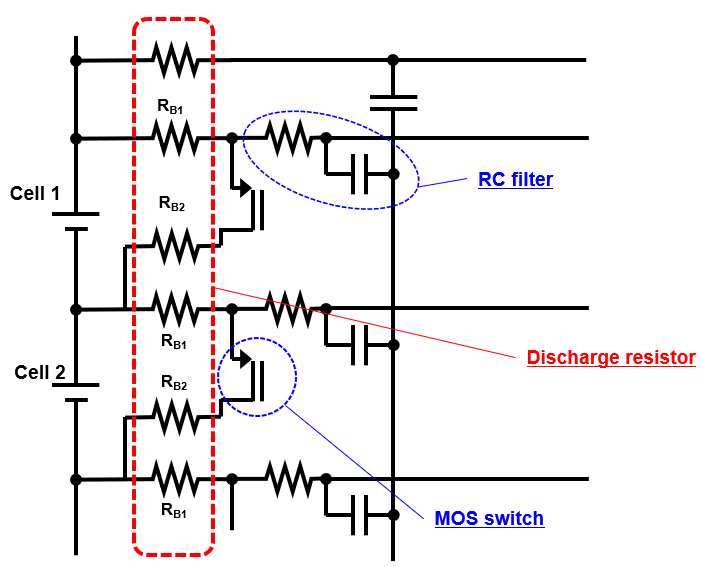
A battery cell is a minimum unit of a battery pack and consists of 1 to 4 units of rechargeable battery cells, a discharge resistor, and a cell balancing circuit, which is a part of BMS. Individual rechargeable batteries in the cell do not always deteriorate uniformly. When the usable capacity of each cell becomes uneven, for example, to 100%, 80%, 80%, or 60%, one of the several solutions is to discharge (consume) the power of higher capacitor cells by using a discharge resistor to match the most deteriorated cell.
The requirement for the discharge resistor in the battery cell is a resistance value of around 10 ohms without particularly requiring accuracy, generally at around 5%, consumed power 1 to 2 watts, by permitting temperature rise to a certain extent. The solution of using several thick film resistors introduced in the previous case would satisfy the requirement, but we proposed the ERJB series with a single high-power type long-side electrode resistor. In the thin film resistors and thick film resistors introduced previously, each of the short sides of a rectangular chip was an electrode, but in the long-side electrode resistors, as the name suggests, the long side is the electrode. Shorter the distance between electrodes receives less chance of crack generation after mounting, but the larger electrode can carry larger power as product features.
As a product lineup of long-side electrode resistors, the ERJB3 series (2012 size) with a rated power of 0.5 W and maximum operating voltage of 150 V, ERJB2 series (3216 size) with a rated power of 0.75 W and maximum operating voltage of 200 V, and ERJB1 series (5025 size) with rated power of 1.0 W and maximum operating voltage of 200 V. Each product series has a rated operating temperature of -55°C to 155°C. As this product is used in the limited space of a battery cell, the use of a single resistor would provide a large advantage.
| Part number | ERJB1 seriesh> | ERJB2 series | ERJB3 series | |
|---|---|---|---|---|
| Size | 5025 | 3216 | 2012 | |
| Rated power | 1.0W 2.0W (≤10Ω) |
0.75W 1.0W (≤10Ω) |
0.5W | |
| Range of resistance value | 10mΩ ~ 10kΩ | 5mΩ ~ 1MΩ | 20mΩ ~ 10Ω | |
| Resistance value tolerance | ± 1%, ± 2%, ± 5% | |||
| TCR (x10-6/°C) |
R<22mΩ | ± 350 | 0~+300 | 0~+300 |
| 22mΩ≦R<47mΩ | ± 200 | ± 200 | 0~+300 | |
| 47mΩ≦R<100mΩ | ± 200, ± 150 (±1%) | 0~+150 | 0~+200 | |
| 100mΩ≦R<1Ω | ±100(±1%) ±200 (±2,±5%) |
0~100(±1%) 0~200 (±2,±5%) |
||
| 1Ω≦R | ±100(±1%) ±200 (±2,±5%) |
±100(±1%) ±200 (±2,±5%) |
||
| Element max. voltage (Max. operating voltage) |
200V | 150V | ||
| Max. overload voltage | 400V | 200V | ||
| Category temperature range (Operating temperature range) |
-55°C to +155°C | |||
In the rapidly advancing EV shift taken as one of global warming prevention means, the BMS is playing a very large role. In such trend of the BMS, Panasonic's technology has achieved chip resistors with compactness, high reliability, and high weather resistance. They have contributed to reliability improvement as well as reduced packaging area and cost, which are highly required by the market.
Related product information
Related information
- Basic Knowledge of Resistors
- Chip resistors that are smaller but which provide more advanced functions are now an important component in solving problems.
- Current Detection Chip Resistors for Responding to the Large Current and High Precision Requirements
- High Precision Chip Resistors that Promote High Performance, Safety Improvement, and Energy Saving
- Anti-sulfurated Chip Resistors That Have Achieved High Reliability by Adopting Gold-based Electrodes and High Palladium-Silver Alloy Electrodes
- Chip resistor’s failure phenomenon/mechanism and solutions (1)
- Chip resistor’s failure phenomenon/mechanism and solutions (2)
- Example of chip resistor adoption (1)– Reduction of the number of parts required and improvement of reliability through the adoption of compact, high withstand voltage, high-precision chip resistors –

Free download of documents
Example of chip resistor adoption
Materials for Example of chip resistor adoption that are posted as technical information in "Optimal Solutions for Circuit Design".
Go to download »